Master the foundational framework that enables all internet communication and data transfer
META INFORMATION
Description: Learn networking fundamentals using the TCP/IP 5-layer model. Understand physical cables, MAC addresses, Ethernet, routers, and how networks communicate.
Target Audience: IT beginners, system administrators, network technicians, cloud engineering aspirants, career changers
Reading Time: 14-16 minutes
Difficulty Level: Intermediate
Prerequisites: Basic understanding of networking concepts (from Networking Fundamentals blog post)
INTRODUCTION
Networks are everywhere. Your phone connects wirelessly. Your computer connects via cable. Thousands of routers move data across the internet. But how does all this actually work?
The answer lies in understanding layers—specifically, the TCP/IP 5-Layer Model, the fundamental framework that governs all network communication.
Think of networks like human communication. Humans follow rules (protocols) so we can understand each other. We speak languages, follow grammar, organize thoughts into sentences. Networks follow the same principle—layers of rules that allow devices to communicate effectively.
The beauty of the 5-layer model is its simplicity. Instead of overwhelming complexity, it breaks networking into five understandable layers, each with a specific purpose. Understand these layers, and you understand how the entire internet works.
For IT professionals and aspiring cloud engineers, the TCP/IP 5-layer model is essential knowledge. It’s not optional—it’s the framework that underlies every system you’ll manage, every network you’ll configure, every troubleshooting decision you’ll make.
Key Takeaway: Networks follow a layered architecture. Master the 5-layer model, and you’ve mastered the foundation of all networking.
THE BIG PICTURE—THE TCP/IP 5-LAYER MODEL
Before exploring individual layers, let’s understand the complete model.
What is the TCP/IP 5-Layer Model?
Definition: A conceptual framework that organizes network communication into five distinct layers, each with specific responsibilities.
Why This Model Matters:
- Simplification: Complex networking made understandable
- Standardization: Everyone uses the same framework
- Troubleshooting: Problems can be isolated to specific layers
- Career Essential: Every IT professional uses this model daily
The Five Layers:
| Layer | Name | Purpose | Key Example |
|---|---|---|---|
| 1 | Physical | Move raw 1s and 0s | Cables, electrical signals |
| 2 | Data Link | Communicate on same network | MAC addresses, Ethernet |
| 3 | Network | Route between networks | IP addresses, routers |
| 4 | Transport | Direct to correct application | TCP, UDP, ports |
| 5 | Application | User-facing services | HTTP, email, DNS |
How They Work Together:
User sends email
    ↓
Layer 5 (Application): Email app prepares message
    ↓
Layer 4 (Transport): TCP ensures reliable delivery
    ↓
Layer 3 (Network): IP routes through internet
    ↓
Layer 2 (Data Link): Ethernet identifies local devices
    ↓
Layer 1 (Physical): Electrical signals on cables
    ↓
Travels across internet
    ↓
Reverse process at destination
    ↓
Email arrives in recipient's inbox
Real-World Analogy—Package Delivery
Understanding the 5-layer model is easier with an analogy:
Sending a Physical Package:
Application Layer: You want to send a birthday gift (email content)
Transport Layer: You package it carefully (TCP ensures it arrives)
Network Layer: You address it to a city across the country (IP routing)
Data Link Layer: Local mail carrier picks it up (Ethernet on local network)
Physical Layer: Truck drives on roads with electrical/mechanical systems (cables)
On the other end, the reverse happens:
Physical Layer: Truck delivers to local post office
Data Link Layer: Local mail carrier delivers to house
Network Layer: Confirmed arrival at correct address
Transport Layer: Unpackaged carefully
Application Layer: Birthday gift opened and enjoyed
Each Layer:
- Adds its own “wrapper” of information (called a header)
- Does its specific job
- Passes to the layer below
- Creates a complete, standardized package
LAYER 1—THE PHYSICAL LAYER
The foundation. The wires. The electrons flowing.
What is the Physical Layer?
Definition: The lowest layer that handles the actual physical transmission of raw data (1s and 0s) across cables and wireless signals.
Key Characteristic: If you can touch it or see it, it’s probably Layer 1.
Physical Layer Components:
| Component | What It Does | Example |
|---|---|---|
| Cables | Transmit electrical signals | Cat5e, Cat6, fiber optic |
| Connectors | Connect cables to devices | RJ45 (Ethernet), SFP (fiber) |
| Network Interface Cards (NICs) | Convert data to electrical signals | Ethernet card in computer |
| Signals | The actual 1s and 0s | Electrical pulses, light pulses |
| Wireless Transmitters | Send signals through air | Wi-Fi antennas |
Layer 1’s Job (Simple Version):
Take digital data (1s and 0s) and convert it to:
- Electrical signals on copper cables, OR
- Light pulses on fiber optic cables, OR
- Radio waves for wireless
Real-World Example:
When you send data:
Computer: "I want to send 01001010"
Layer 1: Converts this to electrical signal
Cable: Carries the signal
Receiving Device: Converts signal back to 01001010
Network Cables—Copper vs. Fiber
Copper Cables (Twisted Pair—Most Common)
How They Work:
- Two copper wires twisted together
- Electrical signals travel through wires
- Twisting reduces electromagnetic interference
- Practical for offices and homes
Categories (Cat):
| Category | Speed | Max Distance | Current Use |
|---|---|---|---|
| Cat5 | 100 Mbps | 100 meters | Legacy, outdated |
| Cat5e | 1 Gbps | 100 meters | Current standard |
| Cat6 | 10 Gbps | 37 meters | Modern, faster |
| Cat6a | 10 Gbps | 100 meters | High-end |
| Cat7 | 10+ Gbps | 100 meters | Future standard |
Why Category Matters:
Better cables (Cat6 vs Cat5e) reduce:
- Crosstalk: Signal interference between wires
- Attenuation: Signal degradation over distance
- Errors: Fewer retransmissions needed
For Your Career: Cat5e is standard for most offices and homes today. Cat6 is increasingly common for new installations.
Fiber Optic Cables
How They Work:
- Glass or plastic fiber core
- Light pulses travel through fiber
- No electromagnetic interference
- Much faster, longer distances
Advantages:
- Speed: Can handle 10 Gbps+ (much faster than copper)
- Distance: Can go 1+ kilometers without degradation
- Immunity: Not affected by electrical interference
- Security: Light signals harder to tap than electrical
Disadvantages:
- Cost: 3-5x more expensive than copper
- Fragility: Can break if bent too much
- Installation: Requires specialized expertise
- Equipment: Specialized transceivers needed
Where Fiber is Used:
- Data center backbone (long distances, high speed)
- Between buildings
- Long-distance internet backbone
- High-security installations
Practical Note: For local networks, copper Cat5e/Cat6 is standard. Fiber is for high-speed, long-distance, or security-critical needs.
Layer 1 Troubleshooting
No Link Light (Cable Disconnected):
Problem: Port shows no link light
Check:
1. Is cable plugged into port? (Obviously, but verify)
2. Is other end plugged in? (Check both ends)
3. Is device powered on? (Device must be on to show link)
4. Is cable damaged? (Try different cable)
If all above check out, port or NIC may be faulty.
Activity Light Flashing:
Meaning: Data is being transmitted
Normal: Should flash when network activity occurs
If constantly flashing: High network usage (could be normal or attack)
If never flashes: No data being transmitted (check connections/configuration)
Slow Network:
Possible Layer 1 causes:
- Cable quality: Cat5 slower than Cat5e/Cat6
- Cable damage: Partially damaged cable works but slower
- Signal degradation: Long cables without repeaters
- Interference: Cables running near electrical equipment
- Hub vs Switch: Hub creates collisions, appears slow
Test: Run speed test. If slow, may be Layer 1 issue.
Check cable quality and distance.
LAYER 2—THE DATA LINK LAYER (ETHERNET)
Now we’re getting organized. Layer 1 was just signals. Layer 2 gives those signals meaning.
What is the Data Link Layer?
Definition: The layer that defines how to interpret Layer 1 signals so nearby devices can communicate with each other on the same network.
Key Protocol: Ethernet
Ethernet is the standard protocol for Local Area Networks (LANs). It defines how devices communicate when connected to the same switch.
Layer 2’s Job:
- Format data into frames (organized packets)
- Add MAC addresses (identify devices on same network)
- Handle error detection (catch corrupted data)
- Manage collisions (when multiple devices transmit simultaneously)
MAC Addresses—Device Identification on Local Network
What is a MAC Address?
Definition: A unique 48-bit identifier assigned to each network device’s network interface card.
Format: Displayed as six pairs of hexadecimal digits (0-9, A-F):
Example: 00:1A:2B:3C:4D:5E
Breaking Down a MAC Address:
First 3 octets: 00:1A:2B
↓ Manufacturer ID (OUI - Organizationally Unique Identifier)
↓ Tells you who made the device
Last 3 octets: 3C:4D:5E
↓ Unique to this specific device
↓ No two devices have identical MAC addresses
Example MAC Identification:
MAC: 00:50:F2:00:00:01
00:50:F2 = Microsoft (manufacturer)
00:00:01 = Specific device #1 from Microsoft
Key Characteristics:
| Characteristic | Details |
|---|---|
| Uniqueness | Globally unique (in theory) |
| Assignment | Burned into NIC at manufacturing |
| Permanence | Usually permanent (though can be spoofed) |
| Scope | Used ONLY on local network (same switch) |
| Does NOT route | Won’t travel across internet |
Why MAC Addresses Exist:
On your local network (office, home), devices need to find each other. Your computer needs to know which physical port on the switch to send data to. MAC addresses solve this.
Real-World Example:
Your computer wants to send data to the printer on same network
Computer: "I need to send this to 192.168.1.50"
(IP address - Layer 3)
Switch: "That's IP 192.168.1.50. What's its MAC address?"
(Switch needs MAC to route on local network - Layer 2)
Lookup: 192.168.1.50 = MAC 00:1A:2B:3C:4D:5E
Switch: "Data destined for MAC 00:1A:2B:3C:4D:5E, send to port 3"
Printer receives data on port 3
Ethernet Transmission Types
Unicast—One to One
Destination: Specific single device
Example: Your computer sends data to printer
Frame: Contains destination MAC address
Switch: Forwards only to that device's port
Result: Only intended device receives data
Multicast—One to Many (Specific)
Destination: Specific group of devices (not all)
Example: Video conference participants
Frame: Contains multicast group address
Switch: Forwards to all devices in group
Result: All group members receive data
Broadcast—One to All
Destination: Every device on network
Example: ARP request ("Who has IP 192.168.1.1?")
Frame: Destination MAC = FF:FF:FF:FF:FF:FF (broadcast address)
Switch: Forwards to ALL ports
Result: Every device on network receives data
Why These Matter:
- Efficiency: Unicast minimizes unnecessary traffic
- Scalability: Multicast allows group communication
- Discovery: Broadcast enables devices to find each other
Ethernet Frames—How Data is Organized at Layer 2
What is an Ethernet Frame?
Definition: A structured package of data that Layer 2 creates to transmit information.
Frame Structure:
[Preamble][Dest MAC][Source MAC][EtherType][Payload][CRC]
Breaking it down:
| Field | Purpose | Size |
|---|---|---|
| Preamble | Synchronizes sender and receiver | 7 bytes |
| Dest MAC | Where frame is going | 6 bytes |
| Source MAC | Where frame is coming from | 6 bytes |
| EtherType | What kind of data payload contains (IPv4, IPv6, ARP) | 2 bytes |
| Payload | The actual data being sent | 46-1500 bytes |
| CRC | Error detection (checksum) | 4 bytes |
Preamble (Layer Sync):
Purpose: Tells receiver "data is coming"
Allows devices to synchronize timing
Ensures both sides ready before data transmission
EtherType (Protocol Identification):
Common values:
0x0800 = IPv4 (Layer 3 - most common)
0x0806 = ARP (Address Resolution Protocol)
0x86DD = IPv6 (Layer 3 - modern)
Device reads EtherType to know what layer to send to next
Payload (The Actual Data):
Contains data from Layer 3 (IP packet)
Minimum 46 bytes (padding if needed)
Maximum 1500 bytes (called MTU - Maximum Transmission Unit)
CRC (Cyclical Redundancy Check):
Mathematical calculation on data
Receiver recalculates CRC on received data
If calculated CRC ≠ received CRC → data was corrupted → frame discarded
This is error detection (not correction)
If frame corrupted, Layer 4 will request retransmission
Real-World Frame Example:
Your computer sends: "Hello, printer!"
Layer 2 creates frame:
[Preamble]
[Destination MAC: 00:1A:2B:3C:4D:5E] ← printer
[Source MAC: AA:BB:CC:DD:EE:FF] ← your computer
[EtherType: 0x0800] ← IPv4 data
[Payload: ... hello printer data ...]
[CRC: calculated checksum]
This complete frame is converted to Layer 1 signals and sent on cable
LAYER 3—THE NETWORK LAYER (IP AND ROUTING)
Now we’re getting between networks. Time to leave the local network and route across the internet.
What is the Network Layer?
Definition: The layer that enables communication between different networks by routing data across the internet using IP addresses.
Key Protocol: IP (Internet Protocol)
Two versions:
- IPv4: Current standard (with limitations)
- IPv6: Future standard (essentially unlimited addresses)
Layer 3’s Job:
- Assign IP addresses (identify networks, not just devices)
- Route data (determine path through multiple networks)
- Fragment data (if packet too large, break it into smaller pieces)
- Handle TTL (prevent infinite loops)
IP Addresses vs. MAC Addresses
Critical Difference:
| Aspect | MAC Address (Layer 2) | IP Address (Layer 3) |
|---|---|---|
| Scope | Local network only | Entire internet |
| Uniqueness | Globally unique | Unique per network |
| Purpose | Find device on same network | Route across networks |
| Routing | No routing | Routers use these |
| Example | 00:1A:2B:3C:4D:5E | 192.168.1.5 |
Real-World Analogy:
IP Address: Your home address (routes mail across country)
MAC Address: Your apartment number (finds apartment in building)
To send mail:
1. Postal system uses address to route across country (IP)
2. Delivery person uses apartment number to find your place (MAC)
Both needed for complete delivery!
Routers—The Network Layer Device
What is a Router?
Definition: A Layer 3 device that connects different networks and forwards data between them based on IP addresses.
Router’s Job:
- Receive packets destined for other networks
- Read destination IP in packet
- Determine best path to destination
- Forward packet toward next router
- Repeat until packet reaches destination
Home Router:
Your home network: 192.168.1.0/24 (devices like 192.168.1.5, 192.168.1.10)
Internet (ISP network): Different network
Your router:
- Connects your home network to ISP
- Translates between two networks
- Routes internet traffic in/out
Core Internet Router (BGP):
Large routers at internet backbone
Use BGP (Border Gateway Protocol)
Know optimal paths to every network
Route millions of packets per second
How Routing Works
Routing Decision Process:
Packet arrives at router with destination IP: 8.8.8.8
Router's routing table:
192.168.1.0/24 → Send out port 1 (local network)
10.0.0.0/8 → Send out port 2
0.0.0.0/0 → Send to ISP router (default route)
Router matches: 8.8.8.8 doesn't match first two
Uses default route: Send to ISP router
ISP router repeats this process
Eventually packet reaches 8.8.8.8
TTL (Time To Live):
Purpose: Prevent infinite loops (packets bouncing forever)
How it works:
Every router decrements TTL by 1
If TTL reaches 0 before reaching destination, packet is discarded
Example:
Initial TTL: 64
Router 1: TTL = 63
Router 2: TTL = 62
Router 3: TTL = 61
... eventually reaches destination or TTL = 0
This prevents "lost" packets from circulating forever
LAYER 4—THE TRANSPORT LAYER
Now we’re directing traffic to specific applications. Email goes to email app, web traffic goes to browser.
What is the Transport Layer?
Definition: The layer that ensures data gets to the correct application on the destination device and handles reliability/speed tradeoffs.
Two Key Protocols:
| Protocol | Reliability | Speed | Use Case |
|---|---|---|---|
| TCP | Guaranteed delivery, ordered | Slower | Email, web pages, files |
| UDP | Best effort, no guarantee | Faster | Video calls, gaming, live streaming |
TCP vs. UDP—A Fundamental Choice
TCP (Transmission Control Protocol):
Characteristics:
- Connection-oriented: Establishes connection before sending data (three-way handshake)
- Reliable: Guarantees data arrives
- Ordered: Packets arrive in order
- Error-checking: Verifies no corruption
- Flow control: Doesn’t overwhelm receiver
How It Works:
1. Sender sends SYN (synchronization request)
2. Receiver responds with SYN-ACK (acknowledgment)
3. Sender sends ACK (acknowledgment)
4. Connection established
5. Data transmission begins
6. Each packet acknowledged by receiver
7. If packet lost, sender retransmits
8. Connection closed with FIN packets
When You Use TCP:
- Email (SMTP)
- Web browsing (HTTP/HTTPS)
- File transfer (FTP)
- SSH/Telnet (remote access)
- Any situation where accuracy matters more than speed
UDP (User Datagram Protocol):
Characteristics:
- Connectionless: No handshake, just send data
- Unreliable: No guarantee packets arrive
- Unordered: Packets may arrive out of order
- No error-checking: Receiver doesn’t verify
- Fast: Minimal overhead
How It Works:
1. Sender just sends data (no connection setup)
2. Receiver gets data (or doesn't)
3. Sender doesn't know if received
4. No retransmission of lost packets
5. Fast and simple
When You Use UDP:
- Video conferencing (Zoom, Google Meet)
- Online gaming (real-time needs)
- Live streaming (video/audio)
- DNS queries (quick lookup)
- Any situation where speed matters more than perfect accuracy
Real-World Comparison:
Watching Netflix (UDP):
Missing one frame: You might see brief glitch
Trade-off: Instant playback worth occasional glitch
Downloading file (TCP):
Missing data: File corrupted, unusable
Trade-off: Wait for complete file, no errors
Ports—Application Identification
What is a Port?
Definition: A number (0-65535) that identifies which application on the device should receive the data.
How Ports Work:
Data arrives: 192.168.1.5:3306
IP: 192.168.1.5 (which device)
Port: 3306 (which application)
Device looks up port 3306: MySQL database
Routes data to MySQL application
Common Port Numbers:
| Port | Protocol | Application | Type |
|---|---|---|---|
| 22 | SSH | Remote access | TCP |
| 25 | SMTP | Email sending | TCP |
| 53 | DNS | Domain lookups | UDP |
| 80 | HTTP | Web browsing | TCP |
| 110 | POP3 | Email receiving | TCP |
| 143 | IMAP | Email receiving | TCP |
| 443 | HTTPS | Secure web | TCP |
| 3306 | MySQL | Database | TCP |
| 3389 | RDP | Remote desktop | TCP |
Port Range Breakdown:
0-1023: Well-known ports (reserved for system services)
1024-49151: Registered ports (applications can register here)
49152-65535: Ephemeral/dynamic ports (temporary use)
Example—Email Sending:
User sends email in client
Client connects to: mail.gmail.com:587 (port 587 = SMTP)
Uses TCP (reliable, must not lose email)
Server receives on port 587
Routes to SMTP application
Email server processes and sends
LAYER 5—THE APPLICATION LAYER
The layer users see. The actual services and applications.
What is the Application Layer?
Definition: The highest layer where user-facing applications and services operate.
Examples of Layer 5 Protocols:
| Protocol | Purpose | Uses Port |
|---|---|---|
| HTTP | Web browsing (insecure) | 80 |
| HTTPS | Web browsing (secure) | 443 |
| SMTP | Email sending | 25, 587 |
| POP3 | Email receiving (older) | 110 |
| IMAP | Email receiving (modern) | 143 |
| DNS | Domain name resolution | 53 |
| FTP | File transfer | 21 |
| SSH | Secure shell / remote access | 22 |
| Telnet | Remote access (insecure) | 23 |
Layer 5’s Job:
- Provide user services (what users actually see)
- Format data for transport 3Handle application-specific logic
- Present to users in understandable way
Real-World Examples:
When you visit google.com:
Layer 5 (Application):
- Browser application launches
- You type google.com
- Browser prepares HTTP request
Layer 4 (Transport):
- Uses TCP (reliable, data must be complete)
- Destination port 443 (HTTPS - secure web)
Layer 3 (Network):
- IP address for google.com determined (via DNS)
- Packet routed across internet
Layer 2 (Data Link):
- Frames created with MAC addresses
- Local switch forwards to gateway
Layer 1 (Physical):
- Electrical signals on cable
[Reverse process on return]
Browser displays: Google search page
PRACTICAL NETWORKING KNOWLEDGE FOR IT PROFESSIONALS
Network Ports and Physical Connections
RJ45 Connector—The Standard
What It Is: Standard connector for Ethernet cables
Pinout (Order Matters!):
Standard: Cat5e/Cat6 twisted pair
8 wires organized in specific order
Two standards: 568A and 568B (both work, pick one and stick with it)
568A: White-Green, Green, White-Orange, Blue, White-Blue, Orange, White-Brown, Brown
568B: White-Orange, Orange, White-Green, Blue, White-Blue, Green, White-brown, Brown
Both work. Consistency matters more than which you choose.
Port LEDs (Indicators):
| LED | Meaning | Status |
|---|---|---|
| Link Light | Cable connection active | Should be solid green when connected |
| Activity Light | Data transmission occurring | Should flash when data transfers |
| Speed Light | Connection speed (on some devices) | Indicates 1Gbps vs 100Mbps |
What Light Status Tells You:
No link light:
- Cable not plugged in
- Cable broken
- Device powered off
- Port faulty
Link light on, no activity:
- Connection good
- But no data being transmitted
Activity light flashing:
- Data is moving (normal during use)
- Constantly flashing: High traffic
- Never flashing: No data (check application)
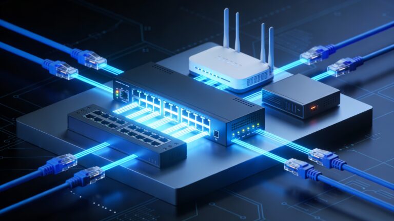
Patch Panel—Central Connection Point
What It Is: Central location where many network cables connect
Purpose:
- Organize cables
- Central point for cable management
- Easier to troubleshoot (can see all connections)
- Common in offices and data centers
Connection Flow:
User's desk → Cable to patch panel
Patch panel → Cable to switch
Switch → Connects users to network
Network Terminology Every IT Professional Needs
LAN (Local Area Network)
Definition: Computers in same location connected together
Scope: Usually single building or small area
Examples: Your home network, office network, school network
Speed: Typically 1 Gbps (fast)
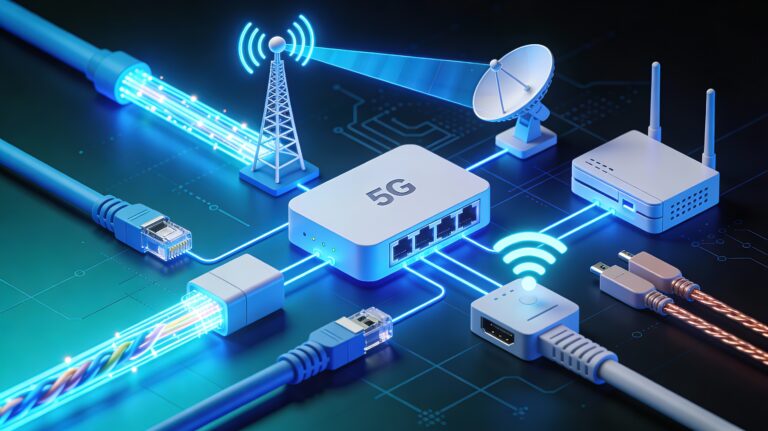
WAN (Wide Area Network)
Definition: Networks in different locations connected together
Scope: Across cities, countries, world
Examples: Company offices in different cities, internet itself
Speed: Typically slower than LAN
Connection: Usually through ISP
ISP (Internet Service Provider)
Definition: Company providing internet access
Role: Connects you to internet backbone
Examples: Comcast, Verizon, AT&T
Provides: Public IP address, internet connectivity, gateway
Protocol (Set of Rules)
Definition: Standardized rules for communication
Purpose: Ensures all devices follow same rules
Examples: TCP, UDP, HTTP, DNS, SSH
Importance: Without protocols, devices couldn't communicate
Duplex (Communication Direction)
Full Duplex: Both devices can transmit and receive simultaneously
- Modern standard
- Both directions at same time
- Allows for higher throughput
Half Duplex: Only one device can transmit at a time
- Older technology
- Devices take turns
- Lower throughput
Example:
Full Duplex: Phone conversation (both talk simultaneously)
Half Duplex: Walkie-talkie (must say "over" before other person can talk)
Common Networking Issues and Layer Diagnosis
Problem: “Network isn’t working”
Troubleshooting by Layer:
Layer 1 (Physical):
- Check cable connection
- Check link light on port
- Test with different cable
- Verify power to device
Layer 2 (Data Link):
- Check MAC address (ipconfig /all)
- Verify switch is working
- Check for port errors (interface down)
Layer 3 (Network):
- Check IP address (ipconfig)
- Verify gateway (should be router IP)
- Test ping to gateway
- Check DNS resolution
Layer 4 (Transport):
- Check if specific port is accessible
- Verify firewall rules
- Test with telnet to port
Layer 5 (Application):
- Verify application is running
- Check application logs
- Restart application
Problem: “Website loads slowly”
Could Be:
- Layer 1: Cable quality (Cat5 vs Cat6), distance
- Layer 2: Switch causing collisions (using hub?)
- Layer 3: Routing issues, high latency
- Layer 4: Packet loss causing retransmissions
- Layer 5: Application inefficiency, poor code
Problem: “Can’t reach specific service”
Check:
- Layer 4: Is port open (firewall rules)?
- Layer 3: Can you reach the device (ping)?
- Layer 2: Are you on same network (check IP/gateway)?
- Layer 1: Is cable connected?
KEY TAKEAWAYS
- TCP/IP 5-Layer Model: Fundamental framework for all networking.
- Layers Work Together: Each layer adds its piece before passing to next layer.
- Layer 1 (Physical): Raw signals on cables (Cat5e, fiber, wireless).
- Layer 2 (Data Link): MAC addresses and Ethernet for local network communication.
- Layer 3 (Network): IP addresses and routers for internet routing.
- Layer 4 (Transport): TCP (reliable) and UDP (fast) for application delivery.
- Layer 5 (Application): HTTP, email, DNS—what users actually use.
- MAC Addresses: Identify devices on local network, don’t route.
- IP Addresses: Identify networks globally, used for routing.
- Routers: Layer 3 devices that connect different networks.
- Ports: Identify which application on a device receives data.
- Ethernet Frames: Structured Layer 2 packages with MAC addresses and error checking.
- TCP vs. UDP: Reliability vs. speed tradeoff.
- CRC: Error detection (not correction) on frames.
- LEDs: Link light (connection), activity light (data transmission).
- Troubleshooting: Always work bottom-up from physical layer.
- Duplex: Full duplex (modern) both directions simultaneously.
- TTL: Prevents infinite loops in routing.
- Protocol: Standardized rules enabling communication.
- The Model Simplifies: Instead of overwhelming complexity, five layers make networking understandable.
CONCLUSION
The TCP/IP 5-layer model isn’t just theory—it’s the practical framework that IT professionals use daily. Understanding networking isn’t about memorizing facts; it’s about understanding the layered architecture that makes modern communication possible.
Every time you send an email, visit a website, or stream a video, all five layers are working together. Data passes through each layer, each adding its own header and handling its responsibility. The elegance of this model is how it simplifies enormous complexity into understandable concepts.
For IT professionals and cloud engineers, mastering this model is foundational. You’ll troubleshoot problems by understanding which layer they’re on. You’ll configure systems knowing how each layer interacts. You’ll design networks understanding how data flows through layers. You’ll optimize performance knowing what each layer contributes.
Your understanding of networking directly impacts your effectiveness in every IT role. Master the 5-layer model, and you’ve mastered the foundation of all modern technology.
ADDITIONAL RESOURCES AND NEXT STEPS
To Deepen Your Networking Knowledge:
- Study OSI model (7 layers, more detailed than TCP/IP 5-layer)
- Learn advanced routing protocols (OSPF, BGP)
- Study network security at each layer
- Explore network segmentation and VLANs
- Learn about network optimization and QoS
Hands-On Practice:
- Use Wireshark to capture and analyze frames
- Build home network with multiple devices
- Configure router (access admin interface)
- Practice troubleshooting with network tools
- Create network diagrams of your network
Useful Tools and Commands:
- ipconfig (Windows) / ifconfig (Mac/Linux): Show network config
- ping: Test connectivity to device
- tracert (Windows) / traceroute (Mac/Linux): Trace route to destination
- nslookup / dig: Perform DNS lookups
- netstat: View network connections
- Wireshark: Capture and analyze packets
Certifications Building on This:
- CompTIA Network+ (essential for networking careers)
- Cisco CCNA (more advanced networking)
- AWS Solutions Architect (cloud networking)
Courses to Consider:
- CompTIA Network+ preparation
- Cisco Networking Fundamentals
- Udemy networking courses
- Linux network administration
- Cloud networking specializations
Recommended Reading:
- “TCP/IP Illustrated” by Stevens (classic reference)
- “The Internet: A Technical Introduction” by Brian Reiman
- CompTIA Network+ study guides
- Cisco networking documentation