Stuck troubleshooting why your network link won’t come up, or confused about which cable to use for a server rack installation? Understanding how devices connect—from simple sensors to enterprise servers—across various physical media is the foundation of effective network support. This guide breaks down complex networking concepts into actionable knowledge, helping you resolve 80% of connectivity problems by mastering just 20% of core principles.
Reading Time: 13 minutes
What You’ll Learn:
- Different types of networked devices and their connection requirements
- Physical media comparison: copper, fiber optics, and wireless technologies
- Ethernet and data link layer fundamentals
- Network interface components and transceivers
- Step-by-step troubleshooting for link-up/link-down issues
- Practical diagnostics with ping, traceroute, and ethtool
Types of Networked Devices
Standard Computers and Mobile Devices
Desktops and laptops typically connect via Ethernet (wired) or Wi-Fi (wireless), using built-in Network Interface Cards (NICs) that handle physical and data link layer functions. Tablets, smartphones, and IoT sensors use varying link technologies depending on their power budget and bandwidth requirements—ranging from cellular networks for wide-area connectivity to Bluetooth and Zigbee for short-range, low-power communication.
Servers and Data Center Equipment
High-performance servers demand redundant network links to prevent single points of failure, often using multiple 10 Gbps or 25 Gbps fiber connections with automatic failover. Data center switches aggregate hundreds of server connections, requiring specialized transceivers (SFPs) to convert electrical signals to optical light for long-distance transmission. Redundancy ensures that if one link fails, traffic automatically shifts to backup paths without service interruption.
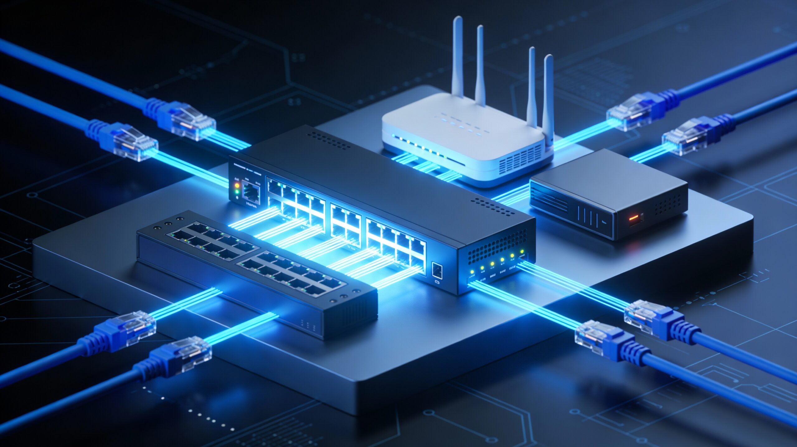
Core Networking Gear
- Routers: Forward packets based on IP addresses, connecting different networks and making routing decisions
- Switches: Forward frames based on MAC addresses within the same network segment, operating at Layer 2
- Firewalls: Filter traffic based on security policies, inspecting packets and blocking unauthorized connections
Specialty Equipment
ATMs, medical imaging devices, industrial controllers, and connected vehicles often use dedicated protocols beyond standard Ethernet. These systems may require specific cable types, voltage levels, or real-time guarantees that consumer networking equipment doesn’t provide.
Physical Layer Media Comparison
Copper Cabling
Twisted Pair (Cat5e/Cat6):
Cat5e supports up to 1 Gbps over 100 meters with 100 MHz bandwidth, making it the baseline for residential and small office environments. The cable uses four twisted copper pairs without advanced shielding, making it susceptible to crosstalk in high-density installations where dozens of cables run parallel in cable trays.
Cat6 delivers 1 Gbps up to 100 meters and 10 Gbps for shorter distances (up to 55 meters) thanks to 250 MHz bandwidth—double that of Cat5e. Tighter wire twists and optional shielding (foil or braided) minimize electromagnetic interference (EMI), critical in data centers with hundreds of adjacent cables.
Coaxial Cable:
Coaxial cabling shields the center conductor with braided metal, making it ideal for cable broadband where TV signals and data share the same infrastructure. The shielding reduces interference, though coax is being phased out in favor of fiber for new installations.
Fiber Optic Cables
Single-Mode Fiber:
Single-mode fiber uses a narrow 9-micron core to transmit light in a single path, achieving distances up to 200 kilometers or more without signal repeaters. The small core diameter requires precise laser light sources, making transceivers more expensive than multimode equivalents. Single-mode excels in long-distance applications like metropolitan area networks (MANs), inter-building campus links, and wide area networks (WANs).
Multimode Fiber:
Multimode fiber features a larger 50-62.5 micron core allowing multiple light rays to travel simultaneously, but this causes signal dispersion that limits practical distances to 400-1,000 meters depending on the grade (OM1-OM5). The larger core accepts light from inexpensive LED sources, reducing transceiver costs by 50-70% compared to single-mode. Multimode dominates LAN backbones within individual buildings and data center rack-to-switch connections where distances stay under 500 meters.
Distance Comparison:
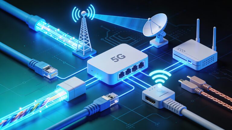
Wireless Technologies
Wi-Fi (802.11):
Wi-Fi operates in unlicensed 2.4 GHz and 5 GHz bands, with modern Wi-Fi 6 (802.11ax) adding 6 GHz spectrum for reduced congestion. Indoor deployments typically achieve 30-50 meter range, while outdoor point-to-point links with directional antennas can reach several kilometers.
Cellular Networks:
3G, 4G LTE, and 5G cellular systems use licensed radio spectrum with handoff capabilities between towers, enabling seamless mobility across cities. Devices intelligently switch between cellular and Wi-Fi based on signal strength, data caps, and battery conservation priorities.
Short-Range IoT Radios:
Bluetooth provides 3 Mbps at ranges up to 100 feet for wearables and accessories, while Zigbee and LoRaWAN offer low-power mesh networking for smart home sensors and agricultural monitoring. NFC (Near Field Communication) operates at extremely short range (2 inches) for contactless payments and device pairing.
Data Link Layer Technologies
Ethernet Frame Structure (IEEE 802.3)
Ethernet frames carry data across LANs with a standardized structure that enables reliable delivery:
- Preamble (7 bytes): Synchronization pattern alerting receivers that a frame is arriving
- Start Frame Delimiter (1 byte): Marks the beginning of the actual frame
- Destination MAC Address (6 bytes): 48-bit identifier of the intended recipient, written as 12 hexadecimal digits like 00:0A:12:34:56:78
- Source MAC Address (6 bytes): Identifies the sender’s network interface
- EtherType (2 bytes): Indicates the protocol type of the payload (e.g., IPv4, IPv6, ARP)
- Payload (46-1500 bytes): The actual data being transmitted
- Frame Check Sequence (4 bytes): CRC error-detection code ensuring frame integrity
MAC addresses allow receiving devices to determine if an incoming frame is intended for them—if not, they discard it without further processing. This filtering at the network interface level prevents unnecessary CPU interrupts and improves performance.
Speed Evolution
Ethernet has evolved dramatically over four decades:
- 10 Mbps: Original Ethernet (1980s)
- 100 Mbps: Fast Ethernet (1990s)
- 1 Gbps: Gigabit Ethernet (2000s) – now standard for desktops
- 10 Gbps+: 10/25/40/100 Gigabit Ethernet for data centers
Wireless LAN (IEEE 802.11)
Infrastructure vs. Ad-hoc Modes:
Infrastructure mode connects client devices through access points (APs) that bridge to wired LANs—the standard enterprise deployment model. Ad-hoc mode creates peer-to-peer connections without centralized APs, useful for temporary networks or disaster recovery scenarios.
Channel Management:
The 2.4 GHz band offers only three non-overlapping channels (1, 6, 11), making careful planning essential in high-density environments like apartment buildings or office parks. Overlapping channels cause interference and throughput degradation—a spectrum analyzer reveals hidden congestion not visible in basic Wi-Fi settings.
Specialized Link Protocols
- SONET/SDH: Synchronous optical networking standards for high-speed carrier networks using ring topologies with automatic failover
- MPLS: Multi-Protocol Label Switching creates label-switched paths for traffic engineering and quality of service guarantees
- Frame Relay & ATM: Legacy WAN protocols largely replaced by Ethernet and fiber solutions
Network Interface Components
NIC (Network Interface Card)
Every networked device contains a NIC providing the physical port and a globally unique MAC address burned into firmware during manufacturing. Modern NICs offload processing tasks like checksum calculation and TCP segmentation from the CPU, dramatically improving throughput for high-speed links.
Transceivers and SFP Modules
Small Form-factor Pluggable (SFP) transceivers are hot-swappable modules enabling flexible connection types without replacing entire network cards:
- SFP (1 Gbps): Most common for gigabit Ethernet, available in copper (RJ45) and fiber (LC connector) variants
- SFP+ (10 Gbps): Data center standard for 10 Gigabit Ethernet using LC duplex fiber connectors
- SFP28 (25 Gbps): Modern server NICs supporting distances from 100 meters to 40 kilometers
- SFP56 (50 Gbps): Backward compatible with SFP and SFP28, supporting distances from 100 meters to 10 kilometers
- QSFP+ (40 Gbps): Quad SFP for high-speed backbone links
- QSFP28 (100 Gbps): Four 25 Gbps lanes aggregated for switch uplinks
SONET-Compatible Modules:
SONET SFP modules support synchronous optical networking standards covering 155 Mbps to 2.488 Gbps, available for multimode, short-reach (SR), intermediate, and long-range applications.
Cabling Standards
Straight-Through Cables: Connect unlike devices (computer to switch, switch to router); wires run directly from pin 1 to pin 1, pin 2 to pin 2, etc.
Crossover Cables: Connect similar devices (computer to computer, switch to switch) by swapping transmit and receive pairs. Modern devices support Auto-MDIX (Medium Dependent Interface Crossover), automatically detecting and adapting to cable type.
Connection Topologies
Point-to-Point Links
Direct connections between two devices use serial protocols, T1 circuits, or fiber connections without intermediate switches. These dedicated links provide predictable latency and bandwidth, common in WAN connections between data centers.
Star Topology
Ethernet LANs use star topologies with a central switch connecting all devices—the most prevalent design in offices and homes. If the central switch fails, all connected devices lose connectivity, making switch redundancy critical for production networks.
Mesh Networks
Full mesh topologies connect every device to every other device, providing maximum redundancy but requiring exponentially more links as node count increases. Partial mesh topologies selectively add redundant paths between critical nodes, balancing reliability and cost. Backbone networks and data centers commonly use partial mesh designs.
Legacy Topologies
Bus topologies (coaxial Ethernet) and ring topologies (Token Ring, SONET/SDH rings) dominated early networks but have been replaced by switched star designs offering higher performance and easier troubleshooting.
Link-Up and Link-Down Troubleshooting
Physical Layer Checks
Step 1: Cable Integrity
Inspect cables for physical damage—cuts, kinks, or crushed sections degrade signal quality and cause intermittent errors. Replace damaged cables immediately rather than attempting repairs, as even minor damage affects high-frequency signals in Cat6 and fiber cables.
Step 2: Link Lights
LED indicators provide immediate status information:
- Green/Solid: Link established successfully
- Amber/Orange: Link negotiated but at reduced speed
- Blinking: Active data transmission
- Off: No physical link detected
Step 3: Connector Quality
Ensure RJ45 connectors have all eight pins fully seated and locked with intact retention clips. Fiber connectors must be clean—dust particles cause signal loss, so use lint-free wipes and inspection scopes before connecting expensive transceivers.
Link Negotiation Problems
Speed and Duplex Mismatches:
Auto-negotiation allows devices to automatically agree on optimal speed and duplex settings, but configuration errors create dangerous mismatches. If one end is manually set to 100 Mbps full-duplex while the other auto-negotiates, the auto-negotiating side defaults to half-duplex per IEEE standards.
This mismatch causes severe performance degradation: the full-duplex side transmits without checking for collisions, while the half-duplex side experiences frequent collisions and retransmissions. Symptoms include 40-60% packet loss, high latency spikes, and occasional timeouts.
⚠ Warning: Gigabit Ethernet requires both sides to auto-negotiate—manual configuration isn’t supported by the standard. Always use auto-negotiation on 1000BASE-T links.
Troubleshooting Steps:
- Verify configuration: Check if either side is manually configured instead of auto-negotiating
- Enable auto-negotiation: Set both sides to auto-negotiate for proper handshake
- Temporary workaround: If auto-negotiation fails, manually configure both sides to identical settings (e.g., both to 100 Mbps full-duplex)
- Check for defective NICs: Driver updates or hardware replacement may be needed if settings don’t persist after reboot
Spanning Tree Protocol and Loop Prevention
Spanning Tree Protocol (STP) prevents broadcast storms in redundant network topologies by selectively blocking redundant paths. The protocol elects a Root Bridge as the logical center, then calculates the lowest-cost path from each switch to the Root Bridge.
How STP Works:
- Root Bridge Election: Switches exchange Bridge Protocol Data Units (BPDUs) to elect the switch with the lowest bridge ID
- Path Cost Calculation: Each switch determines the best path based on link speed—1 Gbps links have lower cost than 100 Mbps links
- Port Blocking: Redundant paths are blocked to prevent loops while remaining ready as backups
When an active link fails, STP recalculates and unblocks backup paths, typically converging within 30-50 seconds. Modern variants like Rapid Spanning Tree Protocol (RSTP) reduce convergence time to under 2 seconds.
✓ Tip: STP is found in industrial-grade fully managed Layer 2 switches—consumer switches lack loop prevention and will create broadcast storms if redundant connections exist.
Signal Quality Issues
Attenuation:
Signal strength degrades over distance due to resistance in copper cables and dispersion in fiber. Cat6 maintains signal quality for 100 meters at 1 Gbps and 55 meters at 10 Gbps—exceeding these distances requires intermediate switches or fiber connections.
Interference:
Electromagnetic interference from motors, fluorescent lights, or parallel power cables induces noise in unshielded twisted pair cabling. Symptoms include increased error rates, retransmissions, and reduced throughput. Solutions include using shielded Cat6A cable, rerouting away from EMI sources, or upgrading to fiber which is immune to electromagnetic interference.
Repeaters and Regenerators:
When distances exceed cable specifications, active repeaters or media converters regenerate signals, effectively resetting the distance limitation. Fiber links can use optical amplifiers or regenerators every 80-120 kilometers on long-haul connections.
Hands-On Troubleshooting Steps
Step 1: Identify Device Type
Note the expected media for each device:
- Desktop/laptop: Cat5e/Cat6 Ethernet or Wi-Fi
- Server: Cat6 or fiber with redundant links
- Data center switch: Fiber SFP+ or SFP28 transceivers
- IoT sensor: Zigbee, LoRaWAN, or Bluetooth
Step 2: Trace the Physical Path
Follow the connection from source to destination:
- NIC in the device
- Cable (copper or fiber)
- Switch port or access point
- Intermediate switches or routers
- Remote endpoint or internet gateway
Document each hop with device names, port numbers, and cable labels for future reference.
Step 3: Inspect Link LEDs
Check physical indicators on both ends of the connection:
- Green = good: Link is up and negotiated properly
- Amber = negotiated: Link established but possibly at reduced speed
- Off = no link: Physical layer failure—check cable, transceiver, or port
Step 4: Use Simple Diagnostic Tools
Ping Test:
ping -c 4 192.168.1.1
Measures basic connectivity and round-trip latency. Successful pings confirm Layer 3 (IP) connectivity but don’t guarantee application-layer functionality.
Traceroute:
traceroute 8.8.8.8
Shows each hop between source and destination, revealing where packets are delayed or dropped.
Ethtool (Linux):
ethtool eth0
Displays NIC speed, duplex mode, link status, and error counters. Compare settings on both ends of a link to identify mismatches.
Mii-tool (Linux):
mii-tool eth0
Checks media-independent interface status and link negotiation.
Windows Command:
netsh interface ipv4 show interfaces
Lists network interfaces with MTU sizes and connection status.
Step 5: Label and Document
Maintain detailed documentation of your network infrastructure:
- Cable runs: Map patch panel ports to wall jacks with cable IDs
- Switch ports: Label which devices connect to each port
- IP addresses: Document static assignments and DHCP ranges
- Vendor/model: Record switch models, transceiver types, and firmware versions
Physical labels on cables and ports save hours during troubleshooting when tracing connections under time pressure.
Key Takeaways
- Cat6 supports 10 Gbps up to 55 meters with 250 MHz bandwidth, making it the recommended choice for new installations despite 20-30% higher cost than Cat5e
- Single-mode fiber reaches 200+ km for inter-building links while multimode (OM4) serves 400-meter data center backbones at significantly lower transceiver costs
- Speed/duplex mismatches cause 40-60% packet loss when one side is manually configured full-duplex while the other auto-negotiates to half-duplex
- Spanning Tree Protocol prevents broadcast storms by blocking redundant paths, converging in 30-50 seconds after link failures
- Link LEDs provide immediate status—green indicates proper negotiation, amber suggests reduced speed, and off reveals physical layer failures
Frequently Asked Questions
Q: Should I use Cat5e or Cat6 for a new office installation?
A: Use Cat6 for new installations to support future 10 Gbps equipment upgrades, especially for runs longer than 30 meters where Cat5e cannot sustain 10 Gbps. The 20-30% cost premium now saves expensive re-cabling later.
Q: When should I choose multimode vs. single-mode fiber?
A: Use multimode for distances under 500 meters within a building or data center to save 50-70% on transceiver costs. Choose single-mode for inter-building campus links or metropolitan networks exceeding 500 meters.
Q: How do I fix persistent link failures?
A: Systematically check physical layer first—cable integrity, clean connectors, proper seating. Then verify link negotiation with ethtool or switch logs, ensuring both sides use identical manual settings or both auto-negotiate.
Q: What causes intermittent connectivity that works sometimes but not others?
A: Duplex mismatches cause this exact symptom—connections work under light load but fail during high traffic when collisions occur. Check for one side manually configured full-duplex while the other auto-negotiated to half-duplex.
Q: Why do my fiber connections show high error rates?
A: Dirty fiber connectors are the #1 cause of fiber issues—inspect with a fiber microscope and clean with lint-free wipes and isopropyl alcohol. Even microscopic dust particles cause significant signal degradation.
Next Steps
Start by documenting your current network topology, then practice basic diagnostics on working connections before attempting repairs under pressure. Consider hands-on labs with old switches and cables to build muscle memory for cable crimping, connector inspection, and link troubleshooting.
Related topics to explore:
- Advanced switch configuration (VLANs, trunking, port security)
- Network monitoring with SNMP and syslog
- Wireless site surveys and heat mapping
- Fiber optic termination and testing certification
Facing specific connectivity challenges? Share your troubleshooting scenario in the comments or subscribe for weekly network support insights tailored to real-world IT environments.